A relay is a switch that is controlled by electricity.
A magnetic field is created by current flowing through the coil of the relay, which attracts a lever and switches the switch contacts.
Relays feature two switch positions and are double throw (changeover) switches since the coil current can be on or off.
The switch connections on the relay are often designated COM(POLE), NC, and NO:
COM/POLE= Common, NC and NO are always connected to this, and it is the switch’s moving portion.
NC = Normally Closed; when the relay coil is not magnetised, the COM/POLE is linked to this.
NO = Normally Open; When the relay coil is MAGNETIZED, the COM/POLE is connected to this, and vice versa.
An electromagnetic or mechanical relay is illustrated in the illustration.


Fig. Relay and its symbol
In a relay, there are five pins.
Two coil ends are stored inside the relay and are represented by pins A and B.
The coil is twisted around a tiny rod, which becomes magnetised when electricity travels through it.
The NC (normally connected) pin is always linked to the COM/POLE.
As electricity passes through coils A and B, the pole connects to the relay’s NO (Normally Open) pin.
Here’s an illustration:
First of all try the following circuit.
This is a circuit for a dark sensor.
![]()
Fig. Dark sensor using two transistors
This is circuit’s output: When light falling on LDR is blocked, the circuit turns on the LED-D1.
Replace LED-D1 and R2- 330R with a relay and a diode at this point.
Reassemble the circuit as indicated in the diagram.
Note: In R3, you can use any resistor between 330R and 4.7K; this resistor is for the dark sensor’s sensitivity.
The circuit below can also be used as a dark sensor. When light is blocked from falling on the LDR, the relay is triggered, and the pole of the relay is linked to the NO pin, providing power to the LED- D1.


Fig. Dark sensor using two transistors and a relay.
Light sensor using relay and transistors
The setup of the relay has been altered in this situation. The NO (normally open) terminal has been left open in this instance. The D1-LED is normally turned on. When the light falling on the LDR is disrupted, the relay’s pole is linked to the NO terminal. As a result, the NC (Normally connected) connection does not receive power, which turns off the D1-LED.

Fig. Light sensor using two transistors and a relay.
If you want the switched circuit to be on while the relay coil is on, connect to COM (pole) and NO.
If you want the switched circuit to be on when the relay coil is off, connect to COM (pole) and NC.
WORKING WITH 220V
Warning: Do not play with 220V AC if you are a novice. For assistance, contact an experienced person.

Fig. Dark sensor circuit for 220V powered lights.
A relay can be used to switch on lights that run on 220V AC. As illustrated in the diagram, the AC-powered light must be linked to the relay.

Fig. Connecting wires on relay
The following video shows a soldered/finished prototype.
PROTECTION DIODE FOR RELAY

Fig. Protection diode in the circuit
Transistors and integrated circuits must be shielded against the high voltage created when a relay coil is turned off for a limited period of time. To offer this protection, a signal diode (e.g., 1N4148, 1N4001, or 1N4007) is connected “backwards” across the relay coil.
When current flows through a relay coil, it produces a magnetic field that abruptly collapses when the current is turned off. The abrupt collapse of the magnetic field causes a transient spike in voltage across the relay coil, which is highly likely to damage transistors and integrated circuits. The protection diode permits the generated voltage to send a short current through the coil (and diode), allowing the magnetic field to fade away more quickly than instantaneously. This keeps the induced voltage from being too high and damaging transistors and integrated circuits.
GENERAL SPECIFICATION OF A RELAY

06VDC- means that the voltage across the relay coil has to be 6V-DC.
50/60Hz- The relay can work under 50/60Hz AC.
7A, 240VAC- The maximum AC current and AC voltage specification that can be passed through NC, NO and pole pins/terminals of relay.
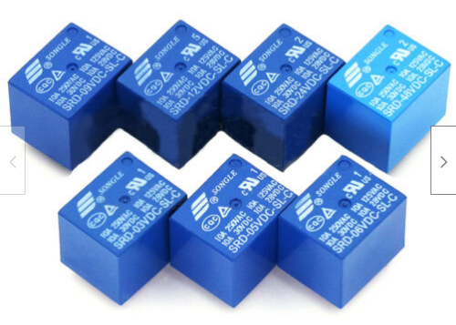
One more example (update 19.3.2014)
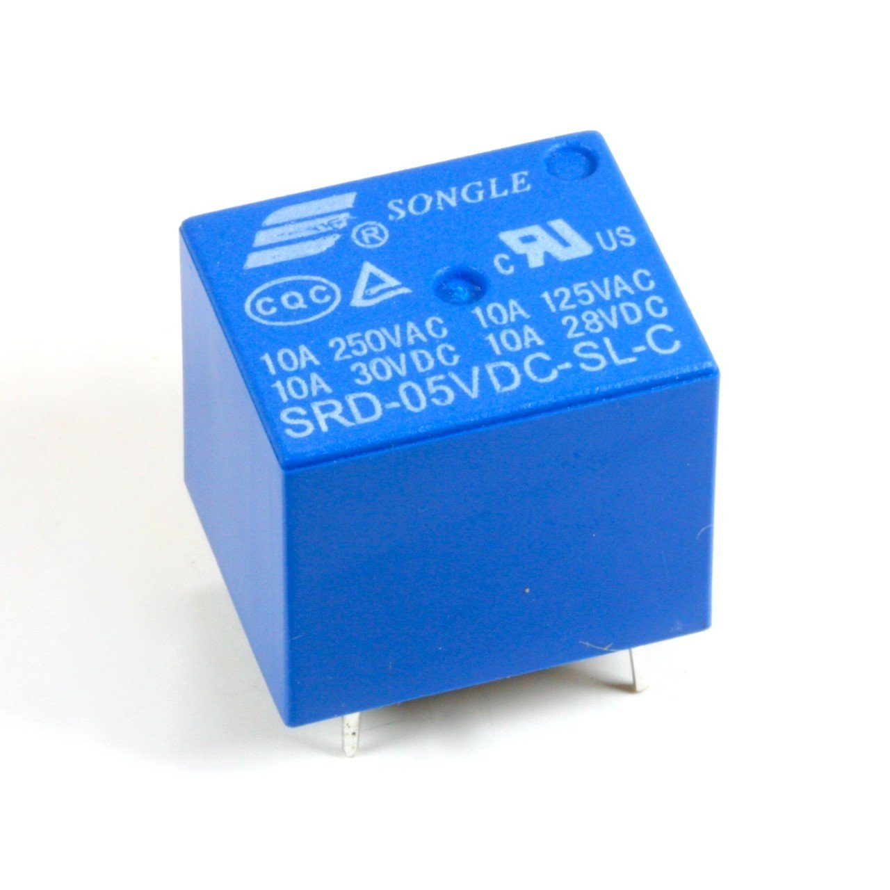
05VDC- It means that you need 5V to activate the relay. In other words, it means that the voltage across the relay coil has to be 5V-DC.
10A 250VAC 10A 125VAC – The maximum AC current and AC voltage specification that can be passed through NC, NO and pole pins/terminals of relay. Some countries have 220V AC power standard, so, it works in those countries also.
10A 30VDC 10A 28VDC- The maximum DC current and DC voltage specification that can be passed through NC, NO and pole pins/terminals of relay.
Tips:
– If you are using a 5-6V relay, use a 6V power supply.
– If you are using a 9V relay, use a 12V power supply.


